[STA] Synchronous Clocks vs. Asynchronous Clocks

![[STA] Synchronous Clocks vs. Asynchronous Clocks](https://images.unsplash.com/photo-1533749047139-189de3cf06d3?crop=entropy&cs=tinysrgb&fit=max&fm=jpg&ixid=M3wxMTc3M3wwfDF8c2VhcmNofDF8fGNsb2NrfGVufDB8fHx8MTc1NTQzMzg1OHww&ixlib=rb-4.1.0&q=80&w=1200)
In the world of digital design, you often hear the terms synchronous clock and asynchronous clock. While simple designs with a single module might use just one clock, modern Systems-on-a-Chip (SoCs) are typically designed with a variety of asynchronous clocks.
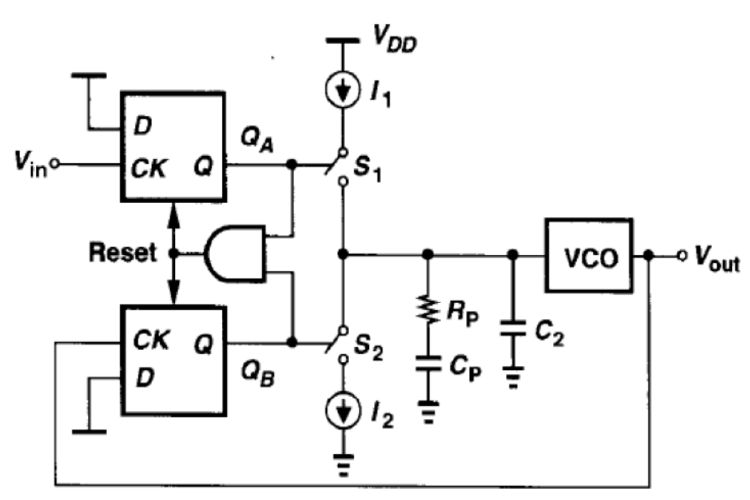
For example, let's look at the Qualcomm Snapdragon 8 Elite AP used in the Samsung Galaxy S25.

This SoC uses multiple clocks running at different frequencies:
- CPU: Big cores at 4.32 to 4.47 GHz, Little cores at 3.53 GHz
- GPU: 1100 to 1200 MHz
- Other IPs: Memory controllers, ISPs (Image Signal Processors), and connectivity IPs likely run at frequencies ranging from 10 Hz to 1+ GHz.
This variety highlights a key point: a single SoC has multiple clocks with different periods. These clocks often originate from different sources.
The Role of PLLs in Generating Clocks
Most high-frequency clocks in digital circuits are sourced from a Phase-Locked Loop (PLL). It's difficult to supply a clock signal directly from the board at frequencies over 100 MHz, so chips generate these high-frequency clocks internally.
A basic PLL takes a reference clock and passes it through several stages:
- Phase Detector (PD): Compares the phase of the reference clock and the PLL's output.
- Charge Pump (CP): Converts the phase difference into an analog voltage.
- Loop Filter (LF): Smoothes the voltage signal.
- Voltage-Controlled Oscillator (VCO): Generates a clock signal whose frequency is proportional to the input voltage.
- Feedback Loop: Sends the VCO output back to the phase detector to ensure the output clock aligns with the reference.
Why Clocks Are Considered Asynchronous
Even if two clocks have the same frequency, they are often considered asynchronous because their physical sources are different. Imagine two separate PLLs on a single chip. Their physical locations on the die are different, and due to manufacturing variations, their individual components (PD, CP, VCO) will have slight differences in their electrical properties, like resistance-capacitance (RC) values.
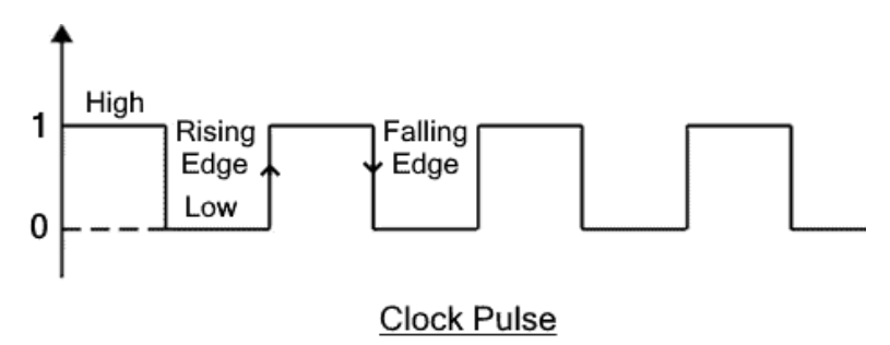
Even if both PLLs receive a reference clock with the exact same period, these subtle differences mean that the rising/falling edges of their output clocks will not be perfectly aligned. This is because:
- The clocks might enter each PLL at slightly different times.
- The physical characteristics of each circuit will cause minor differences in the waveform and timing, leading to jitter.
Ultimately, this means that even clocks with the same frequency must be treated as asynchronous because their edges are not guaranteed to be in perfect phase.
Impact on Timing Analysis
In static timing analysis, clocks with the same period can still be treated as separate clock domains if they are declared separately.
SDC File:
create_clock -name clk1 -period 1.0 [get_ports CLK1]
For example, if you define two clocks with the same period using separate commands in your timing constraints file:
SDC File:
create_clock -name clk1 -period 1.0 [get_ports CLK1]
create_clock -name clk2 -period 1.0 [get_ports CLK2]
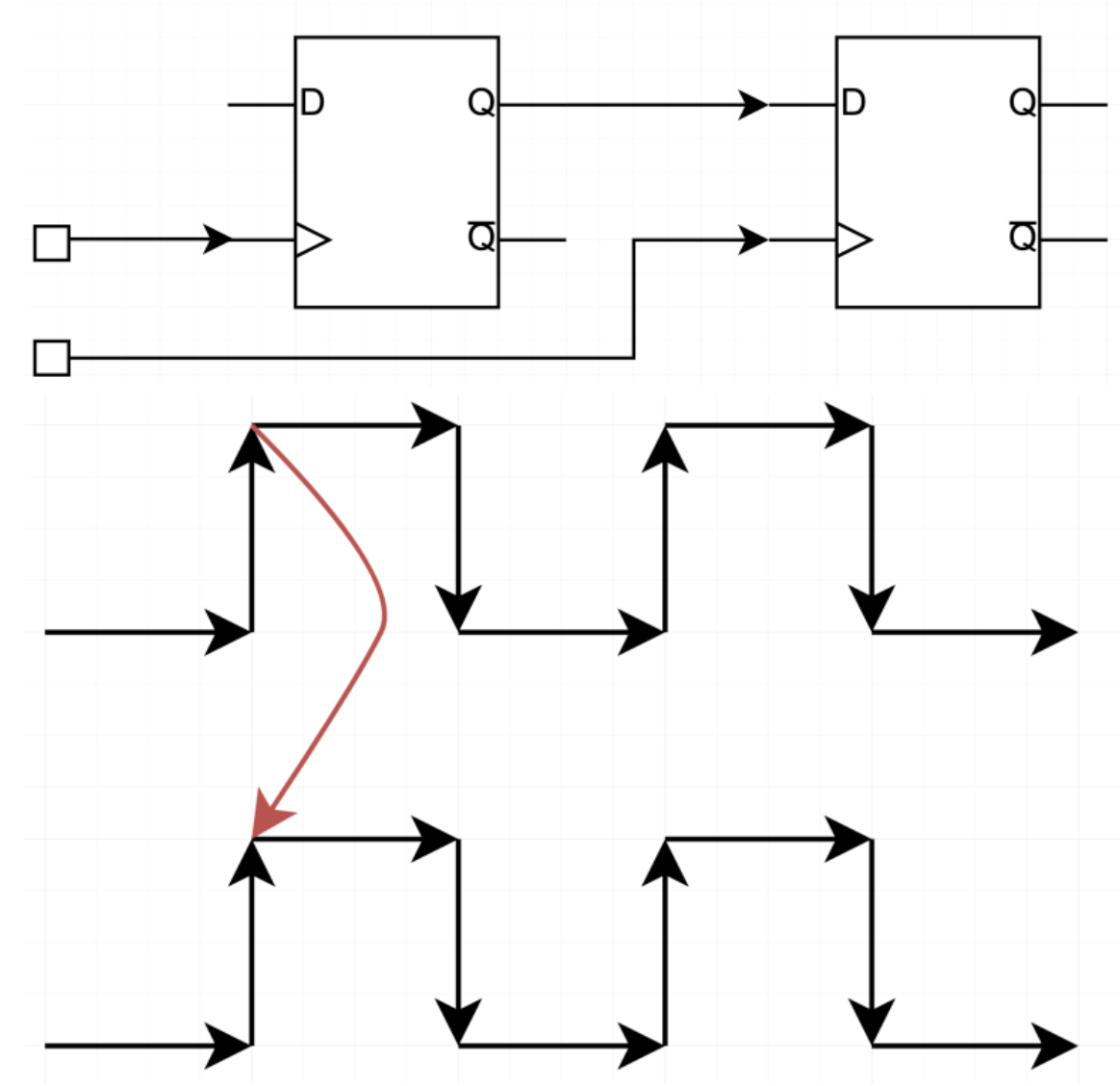
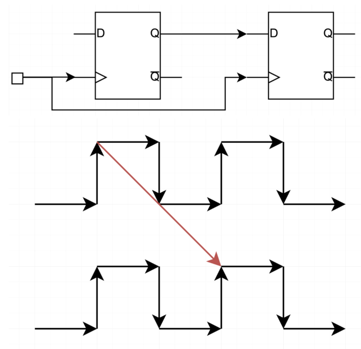
Even with the same period, these two clocks are considered distinct. The timing analysis tool will assume a worst-case scenario where the edges of clk1 and clk2 are completely misaligned. This can lead to timing violations because:
- A flip-flop's setup timing check occurs at the next active edge of its clock.
- In an asynchronous scenario, one clock's active edge (e.g.,
clk1) could toggle immediately before the other clock's edge (clk2), violating the setup time requirement.
So, while the periods might be mathematically identical, the asynchronous nature of the clocks means their edges can be different, often resulting in timing violations in paths between their respective clock domains.


